
Compared to the RF‑/ALUMINUM add-on module (RFEM 5 / RSTAB 8), the following new features have been added to the Aluminum Design add-on for RFEM 6 / RSTAB 9:
- In addition to Eurocode 9, the US standard ADM 2020 is integrated.
- Consideration of the stabilizing effect of purlins and sheets by rotational restraints and shear panels
- Graphical display of the results in the gross section
- Output of the used design check formulas (including a reference to the used equation from the standard)

- Import of materials, cross-sections, and internal forces from RFEM/RSTAB
- Steel design of thin‑walled cross‑sections according to EN 1993‑1‑1:2005 and EN 1993‑1‑5:2006
- Automatic classification of cross-sections according to EN 1993-1-1:2005 + AC:2009, Cl. 5.5.2, and EN 1993-1-5:2006, Cl. 4.4 (cross-section class 4), with optional determination of effective widths according to Annex E for stresses under fy
- Integration of parameters for the following National Annexes:
-
 DIN EN 1993-1-1/NA:2015-08 (Germany)
 -
 ÖNORM B 1993-1-1:2007-02 (Austria)
 -
 NBN EN 1993-1-1/ANB:2010-12 (Belgium)
 -
 BDS EN 1993-1-1/NA:2008 (Bulgaria)
 -
 DS/EN 1993-1-1 DK NA:2015 (Denmark)
 -
 SFS EN 1993-1-1/NA:2005 (Finland)
 -
 NF EN 1993-1-1/NA:2007-05 (France)
 -
 ELOT EN 1993-1-1 (Greece)
 -
 UNI EN 1993-1-1/NA:2008 (Italy)
 -
 LST EN 1993-1-1/NA:2009-04 (Lithuania)
 -
 UNI EN 1993-1-1/NA:2011-02 (Italy)
 -
 MS EN 1993-1-1/NA:2010 (Malaysia)
 -
 NEN EN 1993-1-1/NA:2011-12 (Netherlands)
 - NS EN 1993-1-1/NA:2008-02 (Norway)
-
 PN EN 1993-1-1/NA:2006-06 (Poland)
 -
 NP EN 1993-1-1/NA:2010-03 (Portugal)
 -
 SR EN 1993-1-1/NB:2008-04 (Romania)
 -
 SS EN 1993-1-1/NA:2011-04 (Sweden)
 -
 SS EN 1993-1-1/NA:2010 (Singapore)
 -
 STN EN 1993-1-1/NA:2007-12 (Slovakia)
 -
 SIST EN 1993-1-1/A101:2006-03 (Slovenia)
 -
 UNE EN 1993-1-1/NA:2013-02 (Spain)
 -
 CSN EN 1993-1-1/NA:2007-05 (Czech Republic)
 -
 BS EN 1993-1-1/NA:2008-12 (the United Kingdom)
 -
 CYS EN 1993-1-1/NA:2009-03 (Cyprus)
 - In addition to the National Annexes (NA) listed above, you can also define a specific NA, applying user‑defined limit values and parameters.
- Automatic calculation of all required factors for the design value of flexural buckling resistance Nb,Rd
- Automatic determination of the ideal elastic critical moment Mcr for each member or set of members on every x-location according to the Eigenvalue Method or by comparing moment diagrams. You only have to define the lateral intermediate supports.
- Design of tapered members, unsymmetric sections or sets of members according to the General Method as described in EN 1993-1-1, Cl. 6.3.4
- In the case of the General Method according to Cl. 6.3.4, optional application of "European lateral-torsional buckling curve" according to Naumes, Strohmann, Ungermann, Sedlacek (Stahlbau 77 [2008], pp. 748‑761)
- Rotational restraints can be taken into account (trapezoidal sheeting and purlins)
- Optional consideration of shear panels (for example, trapezoidal sheeting and bracing)
- RF-/STEEL Warping Torsion module extension (license required) for stability analysis according to the second-order analysis as stress analysis including consideration of the 7th degree of freedom (warping)
- Module extension RF-/STEEL Plasticity (license required) for plastic analysis of cross‑sections according to Partial Internal Forces Method (PIFM) and Simplex Method for general cross‑sections (in connection with the RF‑/STEEL Warping Torsion module extension, it is possible to perform the plastic design according to the second‑order analysis)
- Module extension RF-/STEEL Cold-Formed Sections (license required) for ultimate and serviceability limit state designs for cold-formed steel members according to the EN 1993-1-3 and EN 1993-1-5 standards
- ULS design: Selection of fundamental or accidental design situations for each load case, load combination, or result combination
- SLS design: Selection of characteristic, frequent, or quasi-permanent design situations for each load case, load combination, or result combination
- Tension analysis with definable net cross-section areas for member start and end
- Weld designs of welded cross-sections
- Optional calculation of warp spring for nodal support on sets of members
- Graphic of design ratios on cross-section and in RFEM/RSTAB model
- Determination of governing internal forces
- Filter options for graphical results in RFEM/RSTAB
- Representation of design ratios and cross‑section classes in the rendered view
- Color scales in result windows
- Automatic cross-section optimization
- Transfer of optimized cross-sections to RFEM/RSTAB
- Parts lists and quantity surveying
- Direct data export to MS Excel
- Verifiable printout report
- Possibility to include the temperature curve in the report
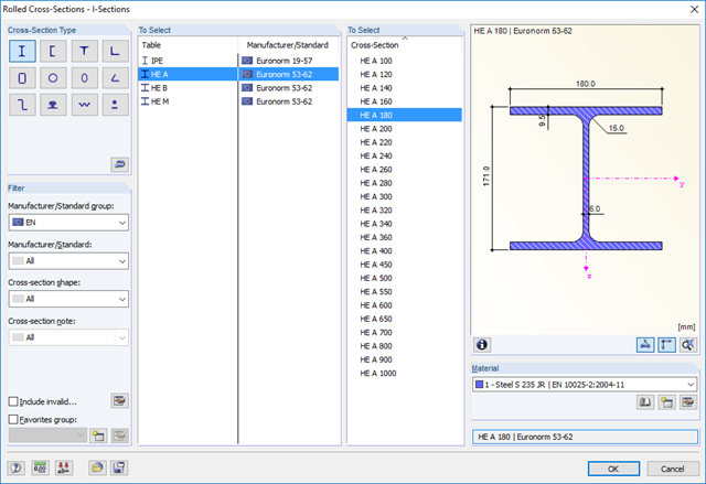
RF-/STEEL EC3 automatically imports the cross-sections defined in RFEM/RSTAB. It is possible to design all thin-walled cross-sections. The program automatically selects the most efficient method according to standards.
The ultimate limit state design takes into account several loads and you can select the interaction designs available in the standard.
The classification of designed cross-sections into Classes 1 to 4 is an essential part of the analysis according to Eurocode 3. This way, you can check the limitation of the design and rotational capacity by means of the local buckling of cross-section parts. RF-/STEEL EC3 determines the c/t-ratios of the cross-section parts subjected to compression stress and performs the classification automatically.
For the stability analysis, you can specify for each member or set of members whether flexural buckling occurs in the y- and/or the z-direction. You can also define additional lateral restraints in order to represent the model close to reality. The slenderness ratio and elastic critical load are determined automatically on the basis of the boundary conditions of RF-/STEEL EC3. The elastic critical moment for lateral-torsional buckling required for the lateral-torsional buckling analysis can be determined automatically or specified manually. The load application point of transverse loads, which has an influence on the torsional resistance, can also be taken into account via the setting in the details. In addition, you can take into account rotational restraints (for example trapezoidal sheeting and purlins) and shear panels (for example trapeziodal sheeting and bracing).
In modern construction, where cross-sections are increasingly slender, the serviceability limit state is an important factor in structural analysis. RF-/STEEL EC3 assigns load cases, load combinations, and result combinations to different design situations. The respective limit deformations are preset in the National Annex and can be adjusted, if necessary. In addition, it is possible to define reference lengths and precambers for the design.
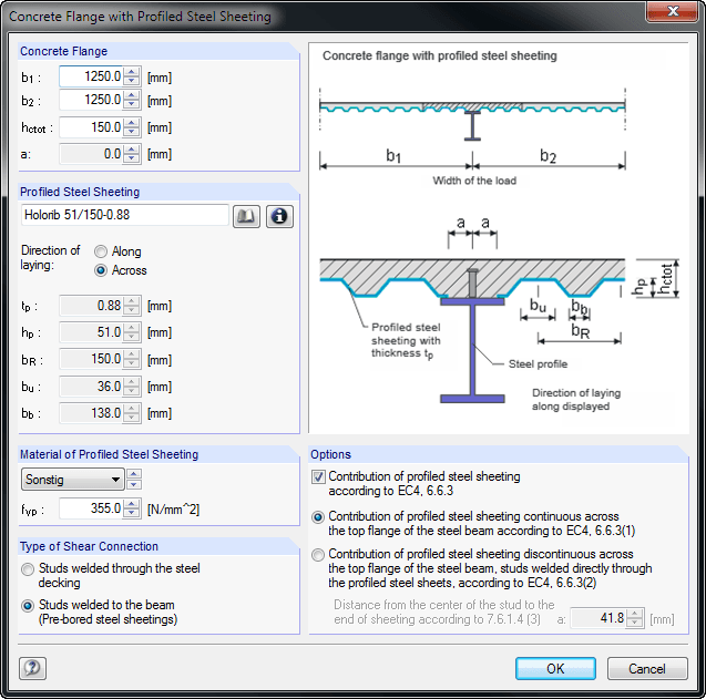
When entering the structural model, you can define single-span and continuous beams with or without cantilevers. Furthermore, it is possible to specify different span lengths with definable boundary conditions (supports, releases) as well as any construction support and moment release in the construction stage. For a complete cross-section, you can create typical composite beam sections on the basis of steel girders (I-sections) with solid concrete flanges, precast plates, trapezoidal sheets, or tapered solid ceilings.
It is also possible to grade cross-sections by means of beam lengths, optionally with concrete encasement. Illustrative figures facilitate the entry of additional transverse reinforcements for trapezoidal sheeting, profile stiffeners, and angled or circular openings in the web. The self-weight is applied automatically when entering loads. In addition, it is possible to consider fixed and variable loads by specifying the concrete age at the beginning of loading for creeping, and to define single, uniform, and trapezoidal loads freely. COMPOSITE-BEAM automatically creates a load combination based on the data of individual load cases.
- For the design according to Eurocode 3, the following National Annexes are available:
-
DIN EN 1993-1-5/NA:2010-12 (Germany)
-
SFS EN 1993-1-5/NA:2006 (Finland)
-
NBN EN 1993-1-5/NA:2011-03 (Belgium)
-
UNI EN 1993-1-5/NA:2011-02 (Italy)
-
NEN EN 1993-1-5/NA:2011-04 (Netherlands)
-
 NS EN 1993-1-5/NA:2009-06 (Norway)
 -
CSN EN 1993-1-5/NA:2008-07 (Czech Republic)
-
CYS EN 1993-1-5/NA:2009-03 (Cyprus)
-
- In addition to the National Annexes listed above, you can also define a specific NA, applying user-defined limit values and parameters.
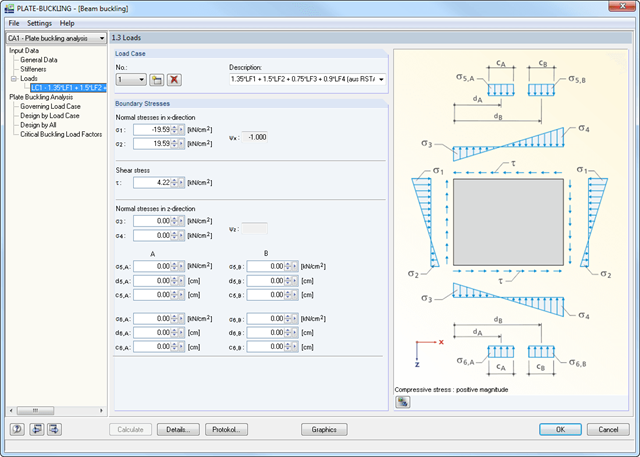
- Import of all relevant internal forces from RFEM/RSTAB by selecting numbers of members and buckling panels with determination of governing boundary stresses
- Summary of stresses in load cases with determination of governing load
- Different materials for stiffener and plate possible
- Import of stiffeners from an extensive library (flat plate and bulb flat steel, angle, T-section, channel, and trapezoidal sheeting)
- Determination of effective widths according to EN 1993-1-5 (Table 4.1 or 4.2) or DIN 18800, Part 3, Eq. (4)
- Optional calculation of critical buckling stresses according to analytical formulas of annexes A.1, A.2, and A.3 of EC 3, or by means of FEA calculation
- Designs (stress, deformation, torsional buckling) of longitudinal and transverse stiffeners
- Optional consideration of buckling effects according to DIN 18800, Part 3, Eq. (13)
- Photo-realistic representation (3D rendering) of buckling panel, including stiffeners, stress conditions, and buckling modes with animation
- Documentation of all input data and results in a verifiable printout report

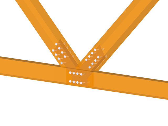
- Design of knee joints, T-joints, cross joints, and continuous column connections with I-shaped sections
- Import of geometry and load data from RFEM/RSTAB or manual specification of the connection (for example, for recalculation without an existing RFEM/RSTAB model)
- Flush top connections or connections with bolt row in extension
- Design of positive and negative frame joint moments
- Various inclinations of right and left horizontal beams as well as application to frames of duopitch and monopitch roofs
- Consideration of additional flanges in a horizontal beam, for example for tapered sections
- Symmetrical and asymmetrical T-joints or cross joints
- Two-sided connection with different cross-section depth on the right and left
- Automatic preliminary design of bolt layout and required stiffening
- Optional design mode with possibility to specify all bolt spacing, welds, and sheet thicknesses
- Screwability check with adjustable dimensions of used wrenches
- Connection classification by stiffness and calculation of the spring stiffness of connections considered in the internal forces determination
- Check up to 45 individual designs (components) of the connection
- Automatic determination of governing internal forces for each individual design
- Controllable connection graphics in rendering mode with specifications of material, sheet thickness, welds, bolt spacing, and all dimensions for construction
- Integrated and flexibly extensible settings of National Annexes according to EN 1993-1-8 standard
- Automatic conversion of internal forces from structural analysis into respective sections, also for eccentric member connections
- Automatic determination of initial stiffness Sj,ini of the connection
- Detailed plausibility check of all dimensions, including specifications of input limits (for example, for edge distances and hole spacing)
- Optional application of compression forces to a column through contact
- Possibility to update the cross-section depth of horizontal beams in case of tapered connections after connection geometry optimization in RF-/FRAME-JOINT Pro
- Structure generator for typical geometries with loading and combinations
- Importing and exporting data from spreadsheet programs such as MS Excel and MS Access
- Connection to various programs compatible with COM, for example, B. CAD systems
- Customized pre- and postprocessing modules
- Processing and results of data in user-defined formats
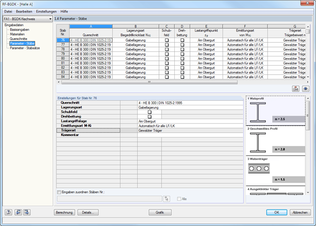
The details for the lateral-torsional buckling analysis are defined separately for members and sets of members. The following parameters can be set:
Support Type/Lateral-Torsional Buckling Load
- Available options are Lateral and torsional restraint, Lateral and torsional restraint or Cantilever
- Special supports are possible by specifying the degree of restraint βz and the degree of warping restraint β0. In this section as well, you can consider the elastic warping restraint of an end plate, a channel section, an angle, a column connection, and a beam cantilever by specifying the geometry dimensions.
- As an alternative, it is also possible to enter the lateral-torsional buckling load NKi or the effective length sKi directly
Shear panel
- A shear panel can be defined from a trapezoidal sheeting, bracing, or a combination of these
- Alternatively, you can enter the shear panel stiffness Sprov directly
Rotational restraint
- Choose between continuous and discontinuous rotational restraint
Position of Positive Transverse Load Application
- The z-coordinate of the load application point can be freely selected in a detailed cross-section graphic. (upper chord, lower chord, centroid)
- Alternatively, you can specify the data by selecting them or entering the data manually.
Beam Type
- For standard sections, the rolled beam, welded beam, castellated beam, notched beam, or tapered beam (web or flange welded) options are available
- For special cross-sections, it is possible to directly enter the beam factor n, the reduced beam factor n, or the reduction factor κM
.png?mw=640&hash=53c64389797699e939283ddbfc3d88485fcbfbf5)
- Full integration in RFEM/RSTAB, including import of all relevant loads
- General stress analysis with warping torsion according to elastic-elastic method
- Stability analysis of planar continuous members for buckling and lateral-torsional buckling
- Determination of critical load factor and thus of Mcr or Ncr (the factor can be used in RF-/LTB for the el/pl design)
- Lateral-torsional buckling analysis of any cross-section (also the SHAPE-THIN cross-sections)
- Design of members and sets of members with applied torsion (for example, crane girder)
- Optional determination of the limit load factor (critical load factor)
- Display of eigenmodes and torsional modes on the rendered cross-section
- Wide range of tools for determining shear panels and rotational restraints (such as corrugated sheets, purlins, bracings)
- Easy determination of discrete springs such as warp springs from end plates or rotational springs from columns
- Graphical selection of load application points on a cross-section (upper chord, centroid, lower chord, or any other point)
- Free arrangement of eccentric nodal and line supports on a cross-section
- Determination of value for inclination or precamber by means of eigenvalue analysis
- Special warping releases applicable for definition of warping conditions on transitions
- Design of hinged, bending resistant, and semi-rigid connections
- Definition of up to 5 steel plates slotted in timber beams
- Up to 8 members connected to one node
- Thickness of steel plate 5 mm – 40 mm
- All sizes of fasteners
- Automatic check of the minimum distance between fasteners
- Optional free definition of fastener distances
- Definition of asymmetrical fastener arrangements (for example, any polygonal chains)
- Graphical visualization of joints in the add-on module and in RFEM/RSTAB
- All required steel and timber designs, including reduction of cross‑section values
- Design of transversal tension reinforcement (for EN 1995‑1‑1 only)
- Export of the member eccentricities to RFEM/RSTAB to be considered in the determination of internal forces
- Dowel length optionally shorter than cross-section width (for wooden plugs)
- DXF Export of Connection Geometry
- Fire resistance design according to EN 1995‑1‑2